04. 在Arduino 設定LoRa 的Arduino函示庫
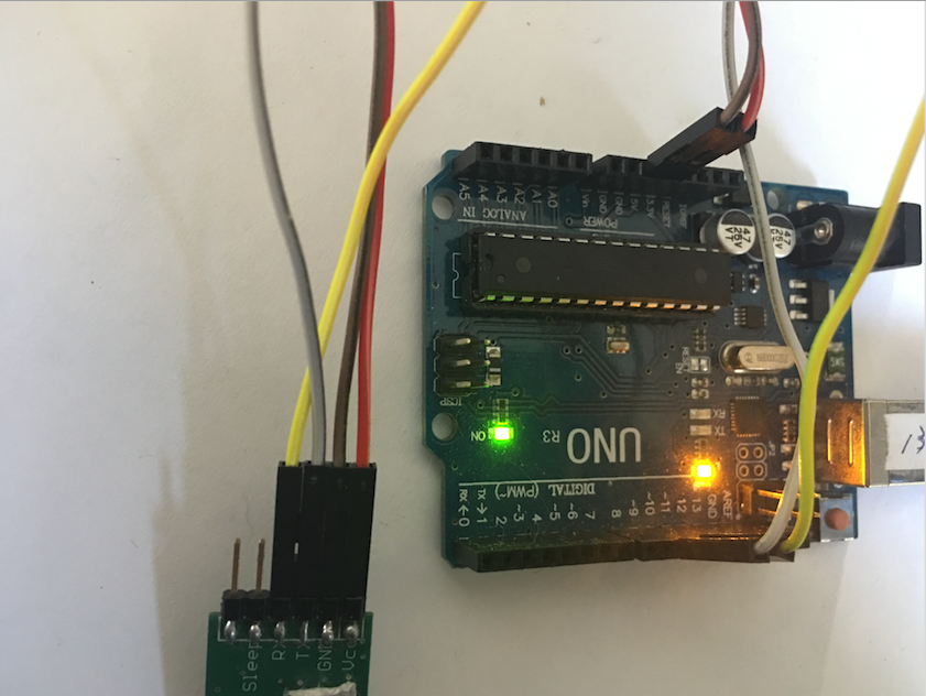
Step1: 在Arduino 連接iFrogLab LoRa 功能, ARDUINO iFrogLab LoRa IL-LORA1272 電源 3.3V Pin 3 接地 GND Pin 1 接收反應 Pin 9 Pin 2 UART Pin 10 Pin 7 UART Pin 11 Pin 8 Step2: 取得LoRa 的Arduino函示庫,這裡。 Arduino 設定方法在此。
我們用Github Arduino 的範例來介紹, 原始程式可以在此取得, /* * iFrogLab F-60 UART Example Code * www.ifroglab.com * * 功能, ARDUINO , iFrogLabF-60 * 電源, 5V ,VCC * 接地, GND ,GND * UART, Pin 10 ,TX * UART, Pin 11 ,RX created 25 Jan 2017 by Powen Ko, www.iFrogLab.com This example code is in the public domain. */ #include
什麼是LoRA,可以看這個iFrogLab 在T 客幫的演講,裡面有詳細的介紹LoRa iFrogLab LoRa的PDF 請點選這裡下載PDF。 iFrogLab LoRa Gateway介紹: iFrogLab LoRa Gateway 主要目的如下: 收集附近iFrogLab LoRa Node 的資料。 把資料存放到內建的MySQL 資料庫中。 並且透過網頁的方法,用圖形化Dashboard的方法,把資料及時顯示出來。 在收到Node 資料的同時,也把資料透過MQTT 的方法,送到MQTT 官網伺服器上。 您的客戶,就能透過MQTT和網頁,收到和看到及時資料。 對貴公司的程式工程師,也能透過MQTT和MySQL 資料庫,收到到資料進行分析和二次開發。 內建iFrogLab IoT 架構,包含iFrogLab ICBlock 和 iFrogLab Dashboard 系統。 完全open source, 免費使用和商業化,可以自行修改和調整。 iFrogLab LoRa Gateway那裡可以取得: 那裡可以取的 這裡 iFrogLab LoRa Gateway 主要架構如下: iFrogLab LoRa LoRa gateway 是用Python 撰寫,source code 在這裡。 把附近Node 只要發送訊號,就能收到。 把資料存放到內建的MySQL 資料庫中。 內建Apache 2 ,並且用PHP 和Google Chart 寫出Dashboard,把資料及時顯示出來,source code
Hello World, iFrogLab LORA, LoRa USB Dongle 超遠端15公里資料傳遞模組 快速上手 如果設備是LoRa USB Dongle 請看此here 如果設備是LoRaIL-LORA1272 請看此here 1.請把LoRa USB Dongle 直接接在數梅派的USB上 2. 透過 $ ls /dev/tty* 確認Raspberry Pi 認出此設備/dev/ttyACM0(如果沒有的話,請使用 Rasbian 2017之後的版本) 2.安裝Python 下載 3.下載Python PySerial 函式庫: python -m pip install pyserial 4.PC/Mac/ Linux下載範例程式 這裡 5. 請執行範例程式中的 ap-Lib-2-lora-send.py 發送 ap-Lib-3-lora-read.py
HI Folks. iFroglab在2016是個豐收的一年,因為我們在LoRa的佈局得到了許多大廠的支持還有幫忙,讓我們可以一步一步的完成IoT的Support Chain(供應鏈) Eclipse Foundation HWTrek IEI Integration Corp. iot.eclipse.org SIEMENS QNAP (依照英文字母排列) 從LoRa的Module到 LoRa USB dongle到QNAP NAS/ IEI的工業電腦到Simons的PLC 控制器。 希望我們在2017年的世界巡迴會走個更加茁壯! 並感謝各位您的支持。
專案完成效果: 原始程式: https://github.com/iFrogLab/IL-LORA1272/blob/master/LoRa-Gateway/Node/LoRa_TsuNaMi_02_GetGY-521-LoRa-Send/LoRa_03_LoRaNode-Send/LoRa_03_LoRaNode-Send.ino 使用方法: 會建議用以下的步驟一步一步的測試和執行: Step1: 先瞭解iFrogLab LoRa IL-LORA1272 的硬體,請依照以下的接腳接線。 Step2: 把Arduino 和 iFrogLab LoRa IL-LORA1272 的硬體,請依照以下的接腳接線。詳細步驟和教學影片請看這裡。 功能 Arduino LoRa 電源 3.3V Pin 3 VCC 接地 GND Pin 1GND UART Pin 10 Pin 7 UART Pin 11 Pin8 Step3: 下載Arduino 下載Arduino 程式,詳細步驟和教學影片請看這裡。 Step4: 測試LoRa 的硬體接線 到Github 下載iFrogLab LoRa Arduino 函數庫iFrogLabLoRaLibrary, 並把iFrogLabLoRaLibrary 複製到Arduino 的函示庫區下,詳細步驟和教學影片請看這裡。 用來確認測試LoRa 的硬體接線 是否正確,並有回傳該晶片的資料。 Step5: 「GY-521 MPU6050 MPU-6050 6DOF 陀螺儀+加速度模組」接線 請把 Arduino 和「GY-521 MPU6050 MPU-6050 6DOF 陀螺儀+加速度模組」的硬體依照下接好。 功能 Arduino GY-521 電源 5V VCC 接地 GND GND A5 SCL A4 SDA GND AD0 Pin 2 INT Step6: 下載「GY-521 MPU6050 MPU-6050 6DOF
Map where your photos were taken and discover local points of interest map where your photos were. Lorem ipsum dolor siter Cum sociis natoque penatibus et magnis parturient montes, it nascetur ridiculus mus. Donec quam felis, ultricies nec, since pellentesque